1975 Evinrude 40 HP Outboards Service Manual, PN 5093, Page 32Get this manual
The second magnet, 180 away and of opposite polarity, passes the driver coil, inducing current flow from the driver coil through points #2 (closed) across the armature plate up through points(closed) and then to the other side of the driver coilThe cam now opens points #2and the voltage rises rapidly across the primary of ignition coil #2The condenser in the primary absorbs the current which would otherwise arc across the opening points (#2)The ignition coil steps up the voltage and fires cylinder #2See Figure 4-6DRI COIL MAGNE 1
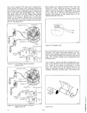
Each ignition coil actually consists of two coilsSee Figure 4-7One, called the primary, consists of relatively few turns of heavy gage copper wireThe other, called the secondary, consists of many turns of fine gage wireThe coils are separated by insulation and mounted on the center leg of "D" shaped laminated iron core
SECOND Y