1974 Johnson 40 HP Outboard Motors Service manual, Page 55Get this manual
CRANKSHAFT INTERNAL "0 "
Figure 5-34Tightening to Specified Torque
CRANKCASE AND CYLINDER
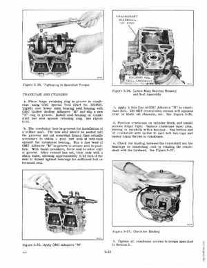
Figure 5-36Lower Main Bearing Housing and Seal Assembly cApply thin line of OMC Adhesive "M" to rankcase face00 NOT overcement; excess will squeeze over to block oil channels, etcSee Figure 5- 35dPosition crankcase on cylinder block, and install screws finger tightReplace crankcase taper pins, driving in carefully with hammerRap bottom end of crankshaft with mallet to seat ball bearings and center crank throws in rankcaseeCheck for binding between the crankshaft and the bearings or connecting rods by rotating the crankshaft with the flywheelSee Figure 5-37
aPlace large retaining ring in groove in crankcase using OMC Special Tool (Part No, 303859)Lightly coat lower main bearing seal housing with OMC Gasket Sealing Adhesive "M" and slip new "0" ring in groove Install seal housing on crankshaft and seat against retaining ringSee Figure '5-10, bThe crankcase face is grooved for installation of rubber sealThe new seal should be seated into the grooves and cut somewhat longer than actually necessary to obtain good butt seal at bot ends against the crankcase bearingRun fine bead of OMC Adhesive "M" in groove to secure seal in pOSition With thumb pressure, force seal to outer edge of grooveAfter cement has set, trim ends with sharp knife, allowing approximately 1 32 inch of the seal to extend against bearings for sufficient butt or terminal seal