1974 Johnson 135 HP Outboard Motors Service manual, Page 106Get this manual
8- 3Move the warm-up lever all the way up to START positionThe mark adjacent to the word START on the throttle cam should point directly at the center of the throttle lever ollerSee insert, Figure 8-3If adjustment is required:
SAFETY WARNING
In rder to insure positive retention in the
Lower the warm-up lever to RUN positionAdjust as necessary by turning the warm -up lever adjustment screw clockwise to retard or cOWlterclockwise to advance the starting speedTo check adjustment repeat Step 1
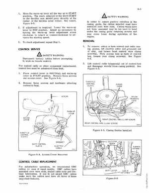
casing guide, the cables selected must have annealed core wire endsCables "Which have not been annealed may be too hard to bend unde the casing guide etaining screws and ay come loose during operation of the engineREMOVALCONTROL SERVICE
SAFETY WARNING Disconnect battery cables before attempting to wo rk on emote controlFor control cable other component replacement, control box mus be unfastened from boat, 2To emove eithe or both control unit cable casIng guides, lift electric cable and grommet out of slotand loosen front control wire clamp screw(s) Thru ccess hole in back of control box, loosen ar clamp screw(s)See Figure 8-5LUt control cable trunnion(s) out of control box and disengage wire(s) from casing guide(s) See Figure 8-5Place control lever in NEUTRAL and warm_up leve in START positionRemove three screws and access coverSee Figure 8-4Remove three screws and hardware attaching control to boatI-SCREWS