1974 Johnson 135 HP Outboard Motors Service manual, Page 77Get this manual
' J2" Figure 6-8AInside Sc rew and Countersunk Screw hRemove gearcase assembly from exhaust housing, being careful not to bend shift rodDo not lose plastic water tube guidesThese are used only to guide water tubes into pump grommets during reassemblyFigure 6-88Gearcase Attachi ng Sc ews
REMOVAL OF EXHAU ST HOUSING and ADAPTER (See Figure 6-10)
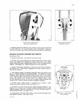
aRemove power headSee Section for instructionsbRemove six screws holding frame and seal assembly to lower motor coverSee Figure 6- 9Remove two lower motor cover rear rubber mount screws and nuts, retaining lower motor cover to exhaust housing adapterSee Figure 6-9Remove lower motor cover assemblycRemove thermostat assembly by removing six screws and washersSee Figure 6- 11Thermostat components are under spring pressureUse care in removaldThe exhaust housing and adapter assemblywhich carries the powe head, is rubber mounted to the swivel bracketTo release the exhaust housing, remove port and starboard lower mount coversSee Figure 6-10Remove rubber mount nuts and washers, two each port and starboardSee Figure 6-10Remove part and starboard upper mount screws attaChing steering arm and pivot to upper rubber mounting (see Figure 6-10)Remove exhaust housing and adapter assemblyeRemove upper rubber mount if necessary from adapterNOTE longer screws are located in front, see Figure 6-11fRemove four screws securing inner exhaust housing to adapterSee Figure 6-11Remove inner exhaust housing through bottom of outer exhaust housingRemove remaining two crews securing adapter to outer exhaust housingSee Figure 6-11gIf necessary to remove water tubes, remove screws attaChing water tube flange to adapterSee Figure 6-12REAR RUBBER MOUN SCREWS