1974 Johnson 135 HP Outboard Motors Service manual, Page 62Get this manual
Always use new gaskets throughout when reassembling the power headPISTONS, WRIST PINS, AND CONNECTING RODS aThe difference between port and tarboard cylinde must be consider ed when assembling pis tons to rodsPis tons must be installed in cylinders with intake ide of deflector toward intake port Oil hole in connecting rod must be toward top of motorSee Figures 5-29 and 5- 31Figure 5- 20Checking Ring Groove Clear ance bApply coat of oil to wrist pin, making ure urface is cleanPlace op or two of oil in each pin hole in the piston
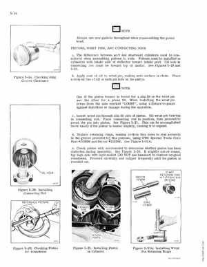
One of the piston bosses Is bor ed for slip !it on the wrist pin and the other for press !itWhen installing the wrist pin press from the side markedLOOSE", using fixture to guard against distortion or dama ge during the operationc Insert wris pin hrough lip fit ide of pistonOil wris pin bearing in connecting odPlace connecting rod in posltlon, then pr oceed to press the pin into pistonSee Figure 5- 21 This can be accomplis hed more easily if the piston is heated Slightly, causing it to expanddReplace etaining ringsmaking ce tain they come to rest ecure ly In the groove provided fat this pur pose, using OMC Special Tools Cone Part -11'3 18600 and Driver 1I3 18599See Figure 5- 31AeCheck piston with micrometer to dete rmine whether piston has been distorted during assemblySee Figure 5- 30If sUghtlyout-of-round, tap high side with Ught mallet (00 NOT use hamme r) to estore riginal oundnessProceed carefully and caliper frequently until the piston is rounded outHOLE ORIVER318599