1974 Johnson 135 HP Outboard Motors Service manual, Page 45Get this manual
STATOR AND TIMER ASSEMBLY REMOVAL
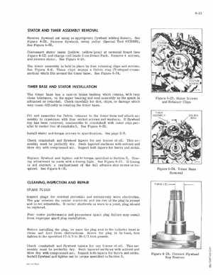
Remove flywhe el nut using an appropriate flywheel holding fixtureSee Figure22Remove flywheel, using puller (Special ool 378103)See Figure22
Disconnect stator leads (yellow, yellow gray) at ter minal board (see Figure 4-1 2) and charge coil leads from Power Pack Remove screws, and remove tator See Figure 4-23 The timer assembly is held in place by four etaining clips and screwsSee Figure 4-6These clips engage Delrin rl.ng (T-shaped cross section) whi ch fits ound the timer base See Fi gure24
TIMER BASE AND STATOR INSTALLATION
The timer base has cast-in brass bushing whi ch rotates, with very
close tolerance, on the upper bearing nd seal assembly as the spark is advanced or retardedCheck carefully for dirt, chips, Or damage which may cause difficulty in otating the timer base