1974 Johnson 135 HP Outboard Motors Service manual, Page 24Get this manual
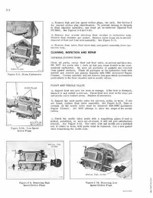
cRemove high and low speed orifice plugs, two each See Section for correct orifice plug identification To prevent damage to threads in float chamber assembly, use fixed jet screwdriver (Special Tool -113 17002) See Figures 3- and 3-10d, Remove four screws attaching float chamber to carburet or body Remove floa chamber and gasketRemove nylon hinge pin to permit removal of float and float arm assembly See Figure 3-11eRemove float valve, floal val ve seat, and gasket assembly from carburetor body
CLEANING, INSPECTION AND REPAIR
GENERAL INSTRUCTIONS
Figure 3-8Drain Carburetor
Clean all parts, except float and fl oat valve, in solve nt and blow dryDO NOT dry parts with cloth as lint may cause trouble in the reassembled carbu retorBe sure all particles of gasket are removed from gasket surfacesFlush all passages in the carburetor body with solvent and remove any gummy deposits with OMC Accessory Engine CleanerCertain solvents willoot remove this gum which accumulates particularly in the float chamber and on needle valvesFLOAT AND NEEDLE VALVE aInspect float and arm for wear or damageIf the float is damaged, discard it and install new oneCheck float rm wear in the hinge pin and needl valve contact areasReplace if necessarybInspect the Inlet needle valve for grooves, nicks, or wear If any are found, replace float valve assemblySee Figure 3-12Gum or varnish on the needle valve must be emoved with OMC Accessory Engine Cleaner00 NOT attempt to alter the shape of the needle valvescCheck the needle valve seat with magnUying glass; if seat is nicked, scratched, or worn out- of-round, it will not give satisfactory se rviceSee Figure 3-13 The valve seat and needle are matched set; if either is worn, both parts must be replacedUse new gasket when reinstalling the needle seat,