1971 Johnson 60HP outboards Service Manual, Page 82Get this manual
TROUBLESHOOTING THE CLIPPER CIRCUIT
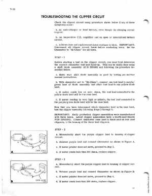
Check the clipper circuit using procedure shown below if any of these symptoms occur: aAn undercharged or dead battery, even though the charging circuit is goodbAn inoperative C.Damplifier and an open or intermittent battery circuitcA blown fuse and replacement fuses continue to blowIMPORTANT: Disconnect all clipper circuit leads before conducting testsset the Ohmmeter to "Hi-Ohms" for all testsSTEPBefore starting test on the clipper circuit, you must first determine the correct ohmmeter test lead hook-upThis can be easily done using shift diode assembly (Pi 383840) and following the procedure described belowaMake sure shift diode assembly is good by testing per service manual instructionsbWith ohmmeter set to "Hi-Ohms", connect one test lead to purple green lead of diode assembly and other test lead to one yellow diode leadcIf meter reads low or zero ohms, the test lead connected to the yellow diode lead will be the case leaddIf meter reading is very high or infinite, the test lead connected to the purple green diode lead will be the case leadNow that you have determined which ohmmeter lead is the case lead, test the clipper assembly following steps through 5IMPORTANT: Early production clipper assemblies were manufactured with three leadsLatest clipper assemblies have fourth lead (black) FOR GROUNDConnect ohmmeter case lead to black lead on four lead clippers, to the housing of the three lead ClippersSTEPaMomentarily short the purple clipper lead to housing of clipper circuitbRelease purple lead and connect Ohmmeter as shown in Figure AcIf meter pOinter does not move, proceed to step 3