1971 Johnson 125HP outboards Service Manual, Page 91Get this manual
BLOCKING AND SHIFT DIODES
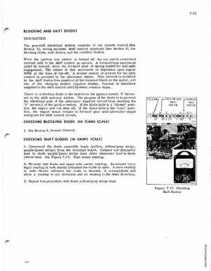
DESCRIPTION The gearshift electrical system consists of the remote control (See Section 8), wiring harness, shift control solenoids (See Section 6), the blocking diode, shift diodes, and the rectifier diodesWhen the ignition key switch is turned off, the key switch controlled current path to the shift control is openedA forward boat movement could be noticed, the forward gear is spring loaded for fail-safe engagementThe extent of this movement is dependent upon engine RPM at the time of cut-offA second source of current for the shift control is provided by the alternator statorThis current is rectified by the shift diodes (two positive) at the terminal block on the motor, and two of the charging system negative diodesCurrent is therefore supplied to the shift control until flywheel rotation stopsThere is blocking diode in the lead from the ignition switch "I" terminal to the shift selector switchThe purpose of the diode is to prevent the electrical path of the alternator supplied circuit from reaching the "I" terminal of the ignition switchIf the diode fails in "closed" position the engine will not shut offIf the diode fails in the "open" position, the engine would remain in forward gear until alternator output energized the sPift control circuitCHECKING BLOCKING DIODE (HI OHMS SCALE)