1971 Johnson 125HP outboards Service Manual, Page 87Get this manual
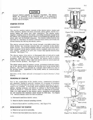
7-7 REFERENCE PICTURE
PLUNGER WINDINGS
Correct battery polarity is extremely importantThe battery MUST be connected so its negative post (-) is connected to groundIf the positive post is connected to ground, the rectifier diodes will be damaged
STARTER SYSTEM
DESCRIPTION The electric starting system consists of the starter motor, starter and choke switches, starter and choke solenoids, safety switch, and the necessary cables and wires with their connectorsThe startermotor supplies cranking power to the motor, converting electrical energy from the battery into mechanical power which is transmitted through the drive pinion gear and the flywheel ring gearThe starter switch controls the operation by activating the starter solenoid which makes and breaks the circuit between the battery and starter motorThe starter solenoid closes the circuit through movable contact disc which strikes two terminal contacts that are connected to the starter motor circuitThe solenoid winding contains many turns of wire which, when energized by the starter switch, exert magnetic pull on the solenoid plunger, causing it to move the contact disc against the terminal contactsSee Figure 7-3The starter motor drive pinion is disengaged when at rest and is made to mesh with the flywheel ring gear by the rotation of the starter motor armatureAfter the motor has started, the starter pinion is driven faster than the starter motor shaft and moves down the screw shaft out of mesh with the flywheelSee Figure 7-4The safety switch opens the starter circuit, preventing accidental engaging of the starter motor, whenever the throttle lever is set beyond start positionThe s.witch is operated by plunger which rides on cam on the throttle leverAdjustment of the safety switch is covered in Section 4, IgnitionOperation of the choke solenoid is discussed in detail in Section 3, Fuel System3404