1971 Johnson 125HP outboards Service Manual, Page 81Get this manual
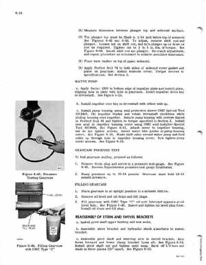
(6) Measure dimension between plunger top and solenoid surface(7) The plunger top must be flush to 164 inch below top of solenoid See Figures 6-42 and 6-44To adjust, remove shift rod and plungerLoosen nut on shift rod, and turn plunger up or down on rod as requiredTighten nut to to inlbsof torqueSee Figure 6-44Install shift rod and plungerRe-check adjustment, and repeat procedure as necessary to achieve specified dimension(8) Place wave washer on top of upper solenoid(9) Apply Perfect Seal #4 to both sides of solenoid cover gasket and place on gearcaseInstall solenoid coverTorque screws to specificationsSee Section 2WATER PUMP aApply Sealer 1000 to bottom edge of impeller plate and install plate, aligning hole in plate with hole in gearcaseInsert impeller drive key in driveshaftSee Figure 6-23bInstall impeller over key in driveshaft with either side upcInstall pump housing using seal protective sleeve OMC Special Tool #312403Oil impeller blades and rotate driveshaft clockwise while sliding housing over impellerSecure pump housing with screws dipped in Perfect Seal #4 and tighten to torque specified in Section 2Install new seal in impeller housing cover using OMC seal installer Special Tool #314640See Figure 6-41Attach cover to impeller housing, but do not tighten screwsInsert water tube guides in pump housing coverSee Figure 6-16Route shift cable around water pump and feed cable up through hole in impeller housing coverNow tighten pump cover screwsSee Figure 6-16GEARCASE PRESSURE TEST To test gearcase sealing, proceed as follows: 1Figure 6-45Pressure Testing Gearcase 2Remove drain plug and screw in pressure test gaugeSee Figure 6-45Stevens Experimental pressure test gauge illustratedPump pressure up to 16-18 poundsGearcase must hold 16-18 pounds pressure