1971 Johnson 125HP outboards Service Manual, Page 61Get this manual
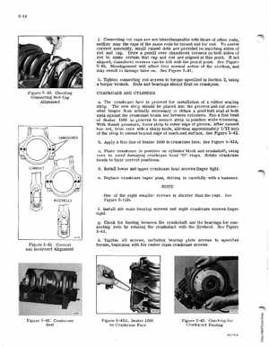
jConnecting rod caps are not interchangeable with those of other rods, neither may the caps of the same rods be turned end for endTo assist correct assembly, small raised dots are provided on matching sides of rod and capDraw pencil over chamfered corners on both sides of rod to make certain that cap and rod are aligned at this pointIf not aligned, chamfered corners can be felt with the pencil pointSee Figure 5-40Misalignment will affect free normal action of the needles, and may result in damage later onSee Figure 5-41
kTighten connecting rod screws to torque specified in Section 2, using torque wrenchRods and bearings should float on crankpinsFigure 5-40Checking Connecting Rod Cap Alignment CRANKCASE AND CYLINDER aThe crankcase face is grooved for installation of rubber sealing stripThe new strip should be placed into the grooves and cut somewhat longer than actually necessary to obtain good butt seal at both ends against the crankcase heads and between cylindersRun fine bead of Sealer 1000 in grooves to secure strip in pOSition while trimmingWith thumb pressure, force strip to outer edge of grooveMter cement has set, trim ends with sharp knife, allOwing apprOXimately 132 inch of the strip to extend beyond edge of machined surfaceSee Figure 5-42bApply thin line of Sealer 1000 to crankcase faceSee Figure 5-42AcPlace crankcase in pOSition on cylinder block and crankshaft, using care to avoid damaging crankcase head "0" ringsRotate crankcase heads to their correct positionsdInstall lower and upper crankcase head screws finger tighteReplace crankcase taper pins, driving in carefully with hammer