1971 Johnson 125HP outboards Service Manual, Page 43Get this manual
REFERENCE PICTURE
REFERENCE PICTURE
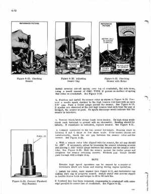
Figure 4-19Checking Sensor
Figure 4-20Adjusting Sensor Gap
Figure 4-21Checking Sensor with Meter
Install reverse cut-off spring over top of crankshaft, flat side down, using small amount of OMC TYPE grease on surface of spring that rides on crankshaftSee Figure 4-18bPosition and install the sensor rotor as shown in Figure 4-19Connect needle spark checker to the high tension coil lead with an open 38" gapPass feeler gauge across the sensorSee Figure 4-19If sparks are observed at the coil high tension lead each time the gap is bridged, the sensor is goodNo spark discharge would indicate that the sensor is defectivecRemove blackwhite stripe leads from sensor .On high ohms scale check each terminal to ground with an ohmmeterReading should be infinityIf resistance is indicated, replace sensorSee Figure 4-21dConnect ohmmeter to the two sensor terminalsReading must be between and ohms on low ohms scaleIf the sensor checks out satisfactorily, check the air gap between the sensor rotor and the sensorSee Figure 4-20eWith sensor rotor lobe aligned with the sensor, the air gap should be .028"If necessary, adjust by loosening the sensor retaining screws and placing .028" feeler gauge between the sensor and the sensor rotor lobeSee Figure 4-20Hold the sensor against the feeler gauge and retighten the sensor retaining screwsRecheck gapGauge should pass through with slight dragNOTE Erratic high speed operation can be caused by sensor or terminals which are loose and moving during engine operationfInstall the rotor, wave washer (see Figure 4-1), and distributor cap making sure cap is properly seatedInstall stator with screws dipped in Loctite Screw Lock and torque to 48 to 60 inch lbsFigure 4-22Correct Flywheel Key Position