1971 Johnson 125HP outboards Service Manual, Page 31Get this manual
To assemble hose clamps, grip clamp firmly with pliersApply slight pressure to hook on top side with screwdriverSqueeze clamp with pliers until hooks interlockSee Figure 3-27CONNECTOR HOUSINGS NOTE
If "0" ring is damaged air will enter fuel line and carburetorMotor will run out of fuel
Figure 3-26
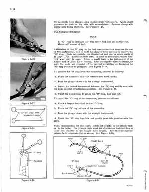
Installation of the "0" ring in the fuel hose connectors requires the use of two instruments, one to hold the plunger down and one to remove the "0" ringBoth instruments are illustrated and can be made easily of 16 gage (116" diameter) steel wireA piece of discarded remote control wire may be usedForm small hook on the bottom end of the longer tool of about 116" radiusAfter cutting the wires to length, be sure the ends are rounded off to prevent scratching or damaging the "0" ring seats or the plungersSee Figure 3- 28To remove the "0" ring from the connector, proceed as follows: aPlace the connector in vise between two wood blocksbPush the plunger down with the straight instrumentcInsert the hooked instrument between the "0" ring and its seat with the hook in flat or horizontal positionSee Figure 3-29dTwist the hook around to grasp the "0" ring, then pull outTo install the "0" ring in the connector, proceed as follows: