1971 Evinrude 40HP outboards Service Manual, Page 26Get this manual
PLU NGER
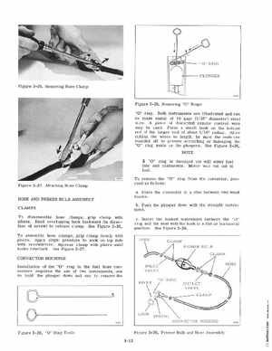
Figure 3-26Removing Hose Clamp
Figure 3-29Removing "0" Rings "0" ring Both instruments are illustrated and can be made easily of 16 gage (1 16" diameter) steel wire piece of discarded remote control wire may be used Form small hook on the bottom end of the longer tool of about 1 16" radius After cutting the wires to lengthbe sure the ends are rounded off to prevent cratching or damaging the "0" ring seats or the plungers See Figure 3-28NOTE
If "0" ring is damaged air will enter fuel line and carburetorMotor will run out of fuel
Figure 3-27 Attaching Hose Clamp HOSE AND PRIMER BULB ASSEMBLY CLAMPS To disassemble hose clamps, grip clamp with pliersBend overlapping hook backward (in direction of arrow) to release clampSee Figure 3-26To assemble hose clamps, grip clamp firmly with pliers Apply slight pressure to hook on top side with screwdriver Squeeze clamp with pliers until hooks interlockSee Figure 3-27CONNECTOR HOUSINGS Installation of the "0" ring in the fuel hose connectors requires the use of two instrumentsone to hold the plunger down and one to remove the