1970 Johnson 115 HP Outboard Motor Service manual, Page 60Get this manual
(6) Repeat teps two (2) through five (5) for each successive empt gr oove until all grooves are filledMaximum allowable clearance (.0025") will not be exceeded as long as fitting Is accomplished by working from the la rgest ize to the smallest ring size(7) Following installation, lubricate each ring and groove liberally with
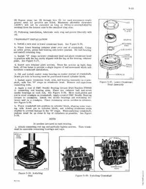
RETAINER PLATE
oilCRANKSHAFT INSTALLATION aInstall new seal in lower ankcase headSee Figure 5-38bPlace lower bearing retainer plate over end of cr ankshaftUSing arbor presspress ball bearing onto lower journalOU ball bearing and install etaining ringcInstall "0" rings on lower crankcase head and place crankcase head in position with the lug cavity aligned with the lug on the bearing re taine plateSee Figur 5-37dInsert new retaine plate screwsDraw the screws up tight, then back off wo turns to provide light degr ee of end movement which will facilitate ranks haft installationeOil and install center main bearing on cente journal of crankshaftDowel pin hole in bearing must be positioned toward cylinder blockfIns tall uppe rankcase head, seal, and bearing assembly on cranks haft, with two "0" rings on crankcase headRe move rod caps from connecting rodsgApply coat of OMC Needle Bearing Grease (Part Number 378642) to connecting rod bear ing areaPlace one retainer half and seven needle bearings on each rodSee Figure 5-39Move each piston and rod to meet crankpin on crankshaftApplyacoat of OMC Needle Bearing Grease to crankpinsInstall wo needle bearings and remaining etainer hal! on rankpinPlace emaining seven needles in retainerSee Figure 5- 39hPlace crankshaft Into position on cylinder block, aligning main bearing with dowel pin in cylinde block, and rotating crankcase heads lightly to prevent damage to the "0ringsWhile installing rankshaft, pistons must be as close to top of cylinders as possibleSee Figure 5- 39NOTE