1970 Johnson 115 HP Outboard Motor Service manual, Page 37Get this manual

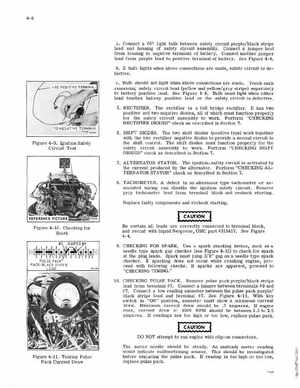
aConnect67 light bulb between safety circuit purple black stripe lead and housing of saret circuit assemblyConnect jumper lead
from housing to negative terminal of batteryConnect another jumper
lead from purple lead to pos itive te rminal of batterySee Figure 4-8 hIf bulb lights when above connections are madesafety circuit is defectiveCBulb should not lig ht when alxlve connections are madeTouch each remaining safety ircuit lead (yellow and yellowgray stripe) separately to batte ry positive leadSee Figure 4-9Bulb must light when ither lead touches battery positive ead Or the safety circ uit is defective5RECTIFIERThe ectifier is full bridge rectifie It has two positive and two negative diodes, all of which mus function properly for the saIety circuit assembly to workPerform "CHECKING RECTIFIER DIODES" check as described in Section 76SHIFT DIODESThe two hift diodes (pos itive type) work together with the two ectifie negative diodes provide second cir cuit to the hift controlThe shift diodes must function properly fo the saIety ircuit assembly to workP rform "CHECKING SHIFT DIODES" check as described In Section 77ALTERNATOR STATOR The ignltion-saIety circuit is activated by the current pr oduced by the alternatorP rform "CHECKING ALTERNATOR STATOR" check as described in Section 7BTACHOMETERA defect in alternator type tachometer or as-