1970 Johnson 115 HP Outboard Motor Service manual, Page 36Get this manual
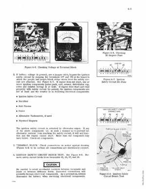
Figure 4- 6Checking 20 Ampere Fuse
Figure 4-5Checking Voltage at Terminal Block
2U battery voltage is present, use jumper wire, bypass the ignition safety circuit by jumping the terminals (17 and -H9) at the board to which the purple and purpleblack stripe wires rrom the safety circuit are attachedSee Figure -7U engine does not start, one or
Figure 4- 7Ignition Safety Circuit By-Pass
more ignition components (pulse pack, coil, sensor, distributor cap, rotor and related wiring) is at raultu engine does start and runs properly with safety circuit bypassed, the ignition components are not at fault and the trouble is in following electrical components: Ignition Safety Circuit Rectifier Shift Diodes Stator Alternator Tachometer, ir used Flywheel Magnets The Ignition safety circuit is actuated by alternator outputU any of the above components fail In such manner as to prevent full alternator current from reaching the safety ircuit, it will not function and the engine cannot startMore than one component may have failedCheck aU components3TERMINAL BLOCKCheck connections on motor against drawing (Figure 4-4) to be ce rtain aU connections are electrically correct4 IGNITION SAFETY CIRCUIT BENCH TESTmove safety Circuit leads from terminals 112,