1970 Evinrude Ski-Twin, Ski-Twin Electric 33 HP Service Manual 4687, Page 54Get this manual
DESCRIPTION RUBBER MOUNTS The exhaust housing assembly, which carries the power head, floats on the steering bracket and pilot shaft assembly on six rubber mounts and two rubber bumpersIn this way, all power head and driveshaft vibrations are isolated and prevented from being transmitted to the stern bracket and boat transomSee Figure 6-1EXHAUST RELIEF Normally, exhaust gases are conducted down through the exhaust housing and out the underwater outlet in the gearcaseThe Siphoning action of the propeller and water provides an unrestricted escape for exhaustHowever, in starting, water in the outlet creates back pressureExhaust relief is provided by another outlet located in the water discharge passage above the water lineSince no water is discharged until after the motor is started, the exhaust gases will initially be discharged through the water outlet
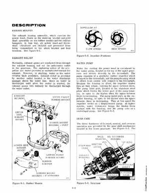
IMPELLER AT
SLOW SPEED
HIGH SPEED
Figure 6-2Impeller Positions WATER PUMP Water for cooling the power head is circulated by the water pump, located at the top of the upper gearcase and driven directly by the driveshaftThe pump consists of synthetic rubber impeller which is keyed to the driveshaft, and the pump hOUSing which is offset from center with respect to the driveshaftBecause the housing is offset, the impeller blades flex as they rotatevarying the space between themThe pump inlet port, located in the stainless steel plate which forms the lower part of the pump housing, is open to the blades when the space between them is increaSingThe pump outlet port, in the impeller housing, is open to the blades when the space between them is decreasingThus at low speed the impeller works as displacement pumpAt higher speeds, water resistance keeps the blades from contact with the housing, and the pump acts as centrifugal pumpSee Figure 6-2GEAR CASE