1965 Evinrude 90 HP StarFlite Service Manual, PN 4206, Page 83Get this manual
bPlace in position against crankcase, and attach mountmg bracket to power head with capscrewcPlace starter drive housing in position on crankcase, and tighten thru-boltsReplace and tighten caps crew attaching starter drive to power headdReconnect starter motor lead ALTERNATOR CHARGING SYSTEM
DESCRIPTION The charging system consists of the alternator, the rectifier diodes which change the alternating current output of the alternator to direct current, the transistorized voltage regulator which serves to keep the charging voltage at safe level, the protective fuses, and the battery itselfThe alternator is made up of two partsthe rotor which is brazed to the inside of the flywheel and turns with it, and the stator assembly which is bolted to the crankcaseSee Figure 7-13The stator assembly is made up of circular field winding and 36 coils wound over laminated iron coreAround this assembly the flywheel-mounted rotor turns, inducing alternating current in the secondary coils
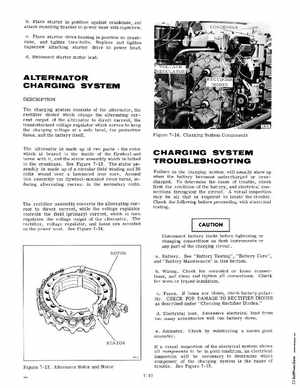
Figure 7-14Charging System Components