1965 Evinrude 90 HP StarFlite Service Manual, PN 4206, Page 46Get this manual
145 OR LESS RETURNS
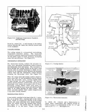
Figure 5-2 Crankcase Compression Chambers and Seal Rings block by dowel pinA ball bearing at the bottom journal absorbs the radial and vertical thrust loads of the crankshaftCOOLING SYSTEM The cooling system is pressurized, recirculating, temperature-controlled systemThe thermostat maintains consistent operating temperatures throughout the entire range of motor operation, increasing motor life and efficiencySee Figure 5-3THERMOSTAT OPERATION The thermostat housing contains the pressure release valve and spring, Vernatherm control element, and thermostat valve and springThe circulation of water through the cooling system by the water pump and the ratio of coolant discharge to intake is controlled by the balanced action between the pressure control valve and the Vernatherm control element actuating the thermostat valveSee Figure 5-4When the power head and cooling system temperatures reach 145 the Vernatherm control element opens the thermostat valve, allowing heated water to pass through the water dischargeThe drop in cooling system pressure caused by the opening of the thermostat valve causes the pressure valve to close, preventing cooling system water from being recirculated through the water pump and allowing fresh water to be drawn through the water intakeThis action provides perfect water jacket temperatures in any water and any weatherTEMPERATURE SWITCH heat switch, installed in the head of the No.3 cylinder, is in series with warning light on the control panelShould an irregularity develop in the COOling system and cause abnormal water jacket temperatures, the switch closes the warning light circuitSee Figure 5-5 The switch may be checked by submerging it in hot waterUsing test light