1965 Evinrude 90 HP StarFlite Service Manual, PN 4206, Page 45Get this manual
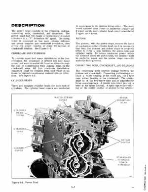
DESCRIPTION The power head consists of the cylinders, pistons, connecting rods, crankshaft, and crankcaseThe power head has two banks of horizontally-mounted cylinders in "V" formation 90 apartThe firing order is combined so that each cylinder delivers one power impulse per crankshaft revolution, thus giving one power impulse at every 90 degrees of crankshaft rotationSee Figure 5-1CRANKCASE AND CYLINDERS To provide equal fuel vapor distribution to the four cylinders, the crankcase is divided into four equal areas, and each is sealed off from the others through the use of compression type sealing rings on the crankshaft websAll four crankcase distribution chambers must be isolated from each other at all times to prevent compression leakage between cylinders See Figure 5-2CYLINDER HEADS There are separate cylinder heads for each bank of cylindersThe cylinder head covers are numbered
to correspond to the ignition firing orderThe starboard cylinder head cover is numbered upper and lower and the port cylinder head cover is numbered upper and lowerPISTONS The pistons, with the piston rings, receive the force of combustion in the cylinder head, so it is necessary that both the pistons and piston rings be properly fitted to form seal between the piston head and cylinder wallsTo retain maximum power within the cylinder above the piston head, the cylinder must be perfectly round and the piston rings correctly seated in their groovesCONNECTING RODS, CRANKSHAFT, AND BEARINGS The connecting rods provide linkage between the pistons and crankshaftConnecting rod bearings include roller bearing at the wrist pin, and split cage roller bearing at the crankshaftThe crankshaft is of the two-throw type and is supported by three main bearingsA double row roller bearing is used at the upper journalA split cage roller bearing at the center journal is aligned to the cylinder