Honda Outboards BF40A/BF50A Service Manual, Page 367Get this manual
BF40A-BF50A
c.ASSEMBLY
Assembly is the reverse order of disassembly
INDICATOR
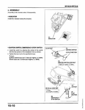
Install the indicator noting the direction
[1] INDICATOR
IGNITION SWITCH, EMERGENCY STOP SWITCH
Install the switch by aligning the cutout of the switch with the flat section of the installation hole as shown Tighten the lock nut to the specified torqueTorque: Ignition switch lock nut: Nm (0.7 kgfm, 5.1 Ibfeft) 16 mm lock nut; 1.5 N-m (0.15 kgf-m, 1.1 IbMt)