Honda Outboards BF40A/BF50A Service Manual, Page 356Get this manual
BF40A-BF50A 2) After installing the power trimtilt assembly, tighten the 78-14 UNF self-locking nut to the specified torqueThen turn it back 1234 turnsTORQUE: 39 N-m (4.0 kgfem, 29 Ibfeft)
[178-14 UNF SELFLOCKING NUT
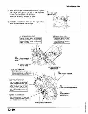
3) Route the power trimtilt motor and trim angle sensor wires and secure them with the clips
[1] WIRE HARNESS CLIP
[2] PURSE LOCK CLIP
Clamp the trim angle sensor wire together with the power trimtilt switch wire and power trimtilt relay wires as shown
Clamp the wires (power trimtilt switch wire, power trimtilt relay wires, and trim angle sensor wire)
TRIM ANGLE SENSOR WIRE [3] POWER TRIMITIL MOTOR WIRE [9] 14 mm TUBE CLIP [3] POWER TRIMITIL MOTOR WIRE