Honda Outboards BF40A/BF50A Service Manual, Page 51Get this manual
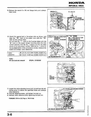
HONDABF35A45A 51 Remove the seven 35 mm flange bolts and cylinder head cover
61 Attach the special tool to the pulser rotor as shown, and
align the "T , mark on the pulser rotor with the "Tt" mark on the cylinder headBe sure that the "T" mark on the flywheel aligns with themark on the engine hanger mounting boss this time (which indicates that the No.1 piston is at the top dead center of its compression stroke)With the No1 piston at the top dead center of the compression stroke, measure the intake and exhaust valve clearancesValve clearance 0.13-0.17 mm (0.005-0.007 inl