Honda BF8, BF9.9 and BF10 Outboard Motors Shop Manual., Page 363Get this manual
15)Install new O-ring on the oil hole cap bolt and tighten the oil hole cap bolt to the specified torque TORQUE: 1.1 N-m (0.11 kgf-m, 0.83 Ibf 'ft)
16)Push the "UP" side and "DM" side of the power tilt switch, and check to see that the piston rod moves smoothly17)Disconnect the motor connector, battery, power tilt relay and switch
O-RING 1.9 9.8 m
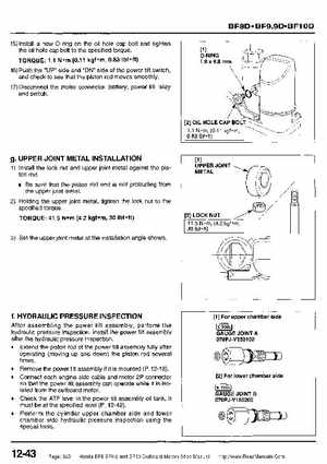
gUPPER JOINT METAL INSTALLATION
1) Install the lock nut and upper joint metal against the piston rodBe sure that the piston rod end is not protruding from the upper joint metal2) Holding the upper joint metal, tighten the lock nut to the specified torque
TORQUE: 41.5 (4.2 kgf m, 30 Ibf -ft) 3) Set the upper joint metal at the installation angle shown
[2] LOCK NUT 41.5 N-m, (4.2 kgf0m, 30 Ibf -fti
-1C PRESSURE IfMSPECTION
After assembling the power tilt assembly, perform the hydraulic pressure inspectionInstall the power tilt assembly after the hydraulic pressure inspectiono Extend the piston rod of the power tilt assembly fully after operating (moving up and down) the piston rod several timeso Remove the power tilt assembly if it is mounted (P12-1 3)o Connect each engine side cable and motor 2P connector so that the power tilt assembly can operate while it is isolated from the outboard motorCheck the ATF level in the power tilt assembly oil tankIt must be at the specified level (P12-42)o Perform the cylinder upper chamber side and lower chamber side hydraulic pressure inspection using the special tools