Honda BF75, BF100, BF8A Outboard Motors Shop Manual, Page 110Get this manual
CONSTRUCTION AND FUNCTION
FUEL SYSTEM
Fuel tank :
The fuel tank assembly consists of the fuel tank (1)filler cap (2)fuel connectors (3), fuel pipe (4)and primer bulb (5) Squeezing the bulb creates vacuum to prime the carburetorThe filler cap incorporates fuel gauge and breather valve to prevent leakage during transport The fuel pipe may be disconnected at the fuel tank for easy handling
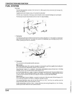
1Fuel pump:
The fuel pump (6) delivers fuel from the fuel tank to the carburetor (7) The pump is diaphragm type driven by the rocker arm The rocker arm pushes the diaphragm up and spring pressure forces it down, pumping fuel into the carburetor
2Carburetor: The carburetor is horizontal butterfly valve typeMain circuit: When the throttle valve (10) is openedenough air is moving through the air guide (8) and carburetor air horn to produce an appreciable vacuum in the venturi (9)
Since the main nozzle (11) is centered in the venturi, atmospheric pressure forces fuel in the float chamber (12) out into the main nozzle via the main jet (13) As the fuel enters the main nozzle, it meets air flowing through the air jet (14) and air bleed (15) in the main nozzleThey mix and flow past the main nozzleThe mixture has high proportion of fuelIt leans out as it mixes with air flowing through the air horn to produce the final mixtureSlow circuit: When the throttle is opened slightlyvacuum is produced in the pilot outlet (16) and bypass (17) Fuel in the float chamber is forced out, flowing through the main jet