Honda BF35A-BF45A Outboard Motors Shop Manual., Page 451Get this manual

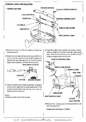
CONTROL CABLE INSTALLATION CONTROL BOX SIDE HOUSING COVER 25 mm TAPPING SCREW (2)
6 mm LOCK PIN (2)
OlTLE CONTROL CABLE
ABLE CLAMP SPACER
SHIFT CONTROL CABLE
IRemove the two 25 tapping screws and housing cover C2) Screw the lock nuts and eye ends more than mm (0.3 in) onto the thread of the control cables and tighten the lock nuts securely to hold the pivotsApply marine grease to the hole of the eye end
41 Install the cable clamp spacer and throttle control
cable by aligning the groove with the cable guide plateThen connect the eye end to throttle arm pin using the washer and mm lock pin