Honda BF35A-BF45A Outboard Motors Shop Manual., Page 51Get this manual
HONDA BF3SAo45A
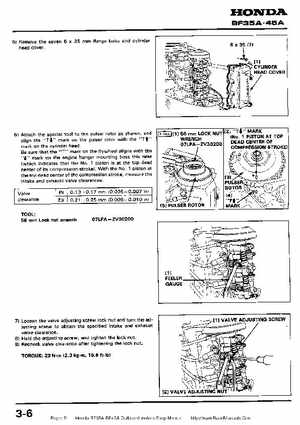
5) Remove the seven 35 flange bolts and cylinder head cover
6) Attach the special tool the pulser rotor as shown, and align the "T4" mark on the pulser rotor with the "Tf" mark on the cylinder headBe sure that the "T" mark on the flywheel aligns with themark on the engine hanger mounting boss this time (which indicates that the No1 piston is at the top dead center of its compression stroke)With the No1 piston at the top dead center of the compression stroke, measure the intake and exhaust valve clearances
Valve clearance