Honda BF20A-BF25A, BF25D-BF30D Outboard Motors Shop Manual., Page 409Get this manual
HONDA BF25A
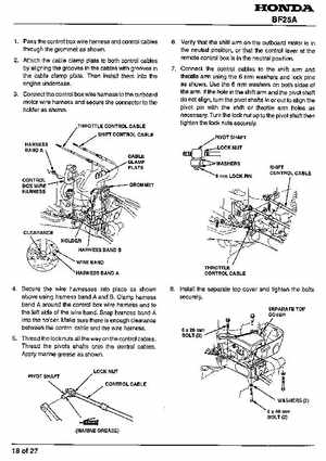
1 Pass the control box wire harness and control cables
6Verify that the shift arm on the outboard motor is in
through the grommet as shown2Attach the cable clamp plate to both control cables by aligning the grooves in the cables with grooves in the cable clamp plateThen install them into the engine undercase
the neutral position, or that the control lever at the remote control box is in the neutral position7 Connect the control cables to the shift arm and throttle arm using the mm washers and lock pins as shownUse the mm washers on both sides of
3Connect the control box wire harness to the outboard motor wire harness and secure the connector to the holder as shown
THROTTLE CONTROL CABLE
the armIf the hole in the shift arm and the pivot shaft do not align, turn the pivot shafts in or out to align the pivot pin with the shift or throttle arm holes as necessaryTurn the lock nut up to the pivot shaft then tighten the lock nuts securely PIVOT SHAFT