Honda BF20A-BF25A, BF25D-BF30D Outboard Motors Shop Manual., Page 49Get this manual
HONDA BF20A-25A
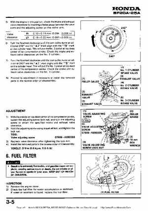
5) With the engine in this position, check the intake and exhaust
valve clearances by inserting feeler gauge between the valve stem and the adjusting screw on the rocker armValve clearance IN 0.1 0-0.14 0.18-0.22 (0.004-0.006 mm (0.007-0.009 in) in)
6) Turn the flywheel clockwise until the cam pulley turns an additional 240 and the "A2" mark align with the "Tf" mark on the cylinder headThis will put the NO2 piston at top dead center of its compression strokeCheck the intake and exhaust valve clearances on the No2 cylinder
7Turn the flywheel clockwise until the cam pulley turns an additional 240 and the2" mark aligns with the "Tf" mark on the cylinder headThis will put the No3 piston at top dead center of its compression strokeCheck the intake and exhaust valve clearances on the No3 cylinder8Proceed adjustment if necessary or install the removed
parts in the reverse order of disassembly
FEELER GAUG
11 No1 CYLINDER INTAKE VALVE 131 EXHAUST VALVE
No2 CYLINDER INTAKE VALVE
EXHAUST VALVE
EXHAUST VALVE