Honda BF115A, BF130A Outboard Motors Shop Manual., Page 158Get this manual
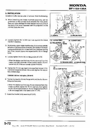
bINSTALLATION Installation is the reverse order of removalNote the following1) When installing the intake manifold assembly, set the protection on the cylinder block between the hose jointsTake care not to damage the area between the hose joints at the back of the vapor separator with the projection on the cylinder block this time
2) Loosely tighten the 10 cap nuts against the intake manifold assembly
[21 PROJECTION
l] (UPPER SIDE)
I41 (LOWER SIDE
3) Position the upper intake manifold stay in contact with the left side of the boss of the crankcase, and position the lower intake manifold stay in contact with the crankcase sealing boltThen, loosely tighten the respective 18 flange bolts4) Loosely tighten the 35 flange bolts (P5-70)When the intake manifold stav A's are removed from the intake manifold, check the 14 washer and 16 mm special bolt (I?5-75) and loosely tighten the boltsPI