Chrysler 70, 75 and 85 HP Outboard Motors Service Manual OB 3438, Page 182Get this manual
4Select the thinnest forward thrust washer available (.054) and place it in the forward gear, which is already in the gear housing This will give reference or starting pointRefer to the parts book for part nu mber and size of th rust washers avai lable5Install prop shaft assembly in gear housing (Shift yoke does not have to be installed at this time) Prop shaft bearing cage should be seated in its counter bore so that the retaining ring grooves are completely exposed AInstall dial indicator post in one of the puller holes on the prop shaft spool (Special Tool NoT 8997F)Figure 34
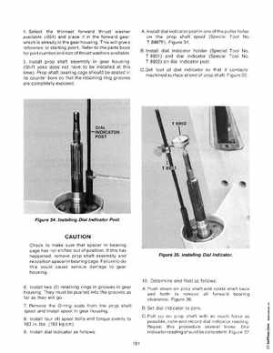
BInstall dial indicator holder (Special Tool NoT 8901) and dial indicator (Special Tool NoT 8902) on dial indicator postC Set foot of dial indicator so that it contacts machined surface at end of prop shaftFigure 35
Figure 34Installing Dial Indicator Post
CAUTION
Check to make sure that spacer in bearing cage has not shifted out of position If this has happened, remove prop shaft assembly and reposition spacer in bearing cage Fai lure to do this could cause serious damage to gear housing 6Install two (2) retaining rings in grooves in gear housingThey must be pushed into the grooves as far as they will go 7Remove the O-ring seals from the prop shaft spool and install spool in gear housing8Install four (4) spool bolts and torque evenly to 160 in Ibs (183 kg cm) 9Install dial indicator as follows181