Chrysler 70, 75 and 85 HP Outboard Motors Service Manual OB 3438, Page 173Get this manual
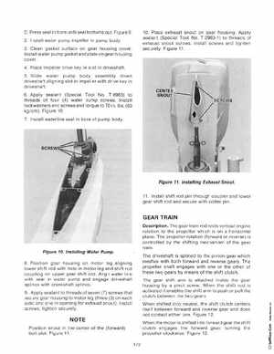
DPress seal in bore until seal bottoms out Figure9 2Install water pump impeller in pump body3Clean gasket surface on gear housing coverInstall water pump gasket and plate on gear housing cover 4Place impeller drive key in slot in driveshaft5Slide water pump body assembly down driveshaft aligning slot in impeller with drive key in riveshaft6Apply sealant (Special Tool NoT 8983) to threads of four (4) water pump screwsInstall lockwashers and screws and torque to 70 in lbs(80 kgcm)Figure 107Install waterline seal in bore of pump body 10Place exhaust snout on gear housingApply sealant (Special Tool NoT 2963-1) to threads of exhaust snout screwsinstall screws and tighte securely Figure 11
Figure 11Installing Exhaust Snout
11 Install shift rod pin through coupler and lower gear shift rod and secure with cotter pin
GEAR TRAIN
DescriptionThe gear train redirects vertical engine rotation to the propeller which is on horizontal plane The propeller rotation (forward or reverse) is controlled by the shifting mechanism of the gear trainThe driveshaft is splined to the pinion gear which meshes with both forward and reverse gears The propeller shaft engages with one or the other of these two gears by means of the shift clutch The gear shift arm is attached inside the gear housing by pivot screwWhen the shift rod is activated it enables the shift arm to push or pull the clutch between the two gearsWhen shifted into neutralthe shift clutch centers itself between forward and reverse gear and does not contact either oneFigure 12When the motor is shifted into forward gear the sh ift clutch engages the forward gear, turning the propeller clockwise Figure 12172