Chrysler 6, 7.5, 180 Sailor Outboard Motors Service Manual, OB 3330, Page 122Get this manual
Subsection
_ GEAR HOUSING (180 SAILOR)
GENERAL
The information in this subsection is concerned with the removal repair and installation of the water pump, and gear train and shift mechanism of the gear housing RemovalTo remove the water pump from the gear housing proceed as follows :
AWARNING
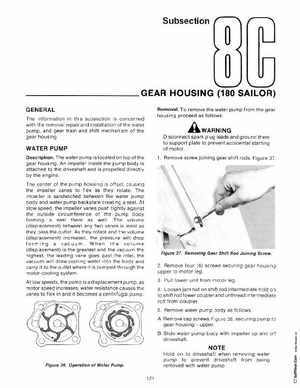
Disconnect spark plug leads and ground them to support plate to prevent accidental starting of motor1Remove screw joining gear shift rods Figure 37
WATER PUMP
DescriptionThe water pump is located on top of the gear housing An impeller inside the pump body is attached to the driveshaft and is propelled directly by the engine The center of the pump housing is offsetcausing the impeller vanes to flex as they rotate The impeller is sandwiched between the water pump body and water pump backplate creating sealAt slow speedthe impeller vanes push tightly against the outside circumference of the pump body forming seal there as wellThe volume (displacement) between any two vanes is least as they pass the outletAs they rotate and the volume (displacement) increasedthe pressure will drop forming vacuum When the volume (displacement) is the greatest and the vacuum the highestthe leading vane goes past the inletthe vacuum will draw cooling water into the body and carry it to the outlet where it is pumped through the motor cooling system At low speedsthe pump is displacement pumpas motor speed increases, water resistance causes the vanes to flex in and it becomes centrifugal pump