Chrysler 6, 7.5, 180 Sailor Outboard Motors Service Manual, OB 3330, Page 116Get this manual
2Install seal in pump body with metal capped end up Seal is installed properly when top of seal is flush to .010" (0 .25 mm) below chamfer in seal bore Figure 20 FLUSH
.010" (0.25 mm)
BELOW FER
Figure 20Proper Installation of Shift Rod Seal
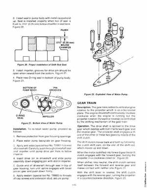
3Install impeller, grooves for drive pin should be open when viewed from the bottom Figure 214Place new O-ring seal in bottom of pump body Figure 21 PIN
Figure 22Exploded View of Water Pump
GEAR TRAIN
DescriptionThe gear train redirects vertical engine rotation to the propeller which is on horizontal plane The engine driveshaft continuously revolves clockwise when the engine is running but the propeller rotation (forward or reverse) is controlled by the shifting mechanism of the gear train OperationThe drive shaft is splined to the drive gear which meshes with both the forward gear and th reverse gea rThe propeller shaft engag es with one of the other of these two gears by means of th shift clutch The shift clutch moves back and forth by followin the clutch shift camon the end of the shift rodwhich moves up and downWhen the motor is shifted into forward gear the shift clutch engages with the forward gear, turn ing the propeller in clockwise direction Figure 23When shifted into neutralthe shift clutch centers itself between the forward and reverse gear and makes contact with neither one Figure 23 With the shift lever in reversethe shift clutch engages with the reverse gearturning the propell in counterclockwise direction Figure 23 115