Chrysler 6, 7.5, 180 Sailor Outboard Motors Service Manual, OB 3330, Page 113Get this manual
InstallationTo install the swivel bracket assembly to the motor, follow the steps outlined for installation of shock mounts Page 00 5Remove motor leg mounting gasket from leg and idle relief baffle from cavity in motor leg InstallationTo install the motor leg casting to the support plate, proceed as follows: 1Place idle relief baffle in cavity on motor leg 2Place new motor leg mounting gasket on motor leg Figure 13
MOTOR LEG CASTING
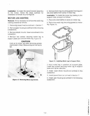
RemovalIf it is necessary to remove the motor leg casting proceed as follows1Remov ing power head as outlined in Section 72Remove gear housing as outlined in the following subsections3Remove shock mountslower as outlined in this subsection 4Remove two screws securing motor leg to support plate and remove motor legFigure 12