Chrysler 6, 7.5, 180 Sailor Outboard Motors Service Manual, OB 3330, Page 101Get this manual
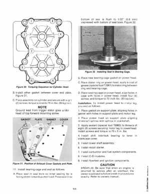
bottom of seal is flush to 1 32(0.8 mm) depressed with bottom of seal bore Figure 32 Figure 32Installing Seal In Bearing Cage
BPlace new bearing cage gasket on power head CPlace stator ring on power headapply coat of grease (special tool T2961) to stator ring between ring and bearing cage
Figure 30Torquing Sequence for Cylinder Head
BInstall other gasket between cover and plate Figure 31
DPlace bearing cage on power head, align holes in
cage with holes in power head, install four (4) screws and torque to 70 inch Ibs(80 kg cm) InstallationTo install power head to motor legproceed as follows1Place gasket on support plate, aligning holes in gasket with holes in support plate and motor leg 2Place power head on support plate aligning driveshaft splines with splines in crankshaft 3Apply sealant (special tool T8983) to threads of eight (8) screws securing motor leg to powerheadInstall screws and torque to 70 SinIbs