Chrysler 6, 7.5, 180 Sailor Outboard Motors Service Manual, OB 3330, Page 56Get this manual
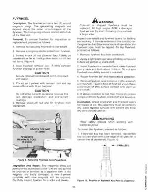
FLYWHEEL DescriptionThe flywheel contains two (2) sets of magnetic ringsThe generating magnets are located about the outer circumference of the flywheelThe timing magnets are located at the hub of the flywheelRemovalTo remove flywheel for inspection or replacementproceed as follows 1Remove nut securing flywheel to crankshaft2Remove emergency starter collar from flywheel3Thread knock off nut (Special Tool T2909) on crankshaft as far as it will go then back nut off two full turnsFigure 94Slide flywheel removal tool (T2989) between flywheel and top of power head
AWARNING
Cracked or chipped flywheels must be replaced At high engine RPM damaged flywheel can fly apart, throwing shrapnel over large areaInspect crankshaft and flywheel tapers for fretting and workingIf there is evidence of this condition or if engine has had 25 or more hours of operationthe flywheel bore must be lappedTo lap flywheelproceed as follows1Remove flywheel key from crankshaft 2Applya light coating of valve grinding compound to tapered portion of crankshaft3Install flywheel on crankshaft and rotate flywheel gently back and forth about 1 turn Do not spin flywheel completely around crankshaft4Rotate flywheel 90 and repeat above operation 5Remove flywheel, wipe compound off crankshaft and flywheelTaper in bore of flywheel should have minimum of 90 surface contact with taper on crankshaft6If above condition is met, then thoroughly clean compound from flywheel, crankshaft and keyways InstallationCheck crankshaft and flywheel tapers for traces of oilThis assembly must be perfectly drySwab tapered surfaces with solvent and blow dry with compressed air