Chrysler 6, 7.5, 180 Sailor Outboard Motors Service Manual, OB 3330, Page 46Get this manual
Subsection
ELECTRICAL SYSTEM
GENERAL
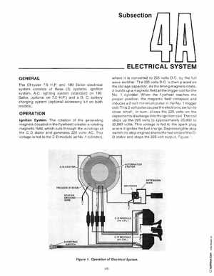
The Chrysler 7.5 H.Pand 180 Sailor electrical system consists of three (3) systemsignition system, A.Clighting system (standard on 180 Sailor, optional on 7.5 H.P and DCbattery charging system (optional accessory kit on both models) where it is converted to 225 volts D.Cby the full wave rectifierThe 225 volts D.Cis then placed on the storage capacitorAs the timing magnets rotate, it builds up magnetic field at the trigger coil fo th No1 cylinderWhen the flywheel reach es th proper position, the magnetic field collapses and induces volt minimum pulse in the NO1 trigg er coilThis volt pulse causes the electronic switch to close whichin turnallows the 225 volts on th capacitor to discharge into the ignition coilThe coil steps up the 225 volts to approximately 25 ,000 to 32 ,000 voltsThis voltage is fed to the spark plug where it ignites the fuel charge Depressing the stop switch (to stop engine) shorts the two ends of th CD stator and stops the 225 volt output, Figure 1