Chrysler 25 and 30 HP Outboard Motors Service Manual OB 1894, Page 86Get this manual
SECTION XIV (Cont NOTE
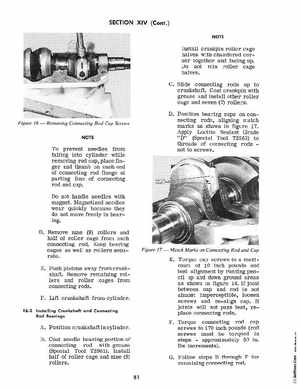
Install crankpin roller cage halves with chamfered corner together and facing upDo not mix roller cage halvesCSlide connecting rods up to crankshaftCoat crankpin with grease and install other roller cage and seven (7) rollersDPosition bearing caps on connecting rods, aligning match marks as shown in figure 17Apply Loctite Sealant Grade "D" (Special Tool T2963) to threads of connecting rods not to screws
Figure 16 -
Removing Connecting Rod Cap Screws
To prevent needles from falling into cylinder while removing rod cap, place finger and thumb on each end of connecting rod flange at parting line of connecting rod and capDo not handle needles with magnetMagnetized needles wear quickly because they do not move freely in bearingDRemove nine (9) rollers and half of roller cage from each connecting rodKeep bearing cages as well as rollers separateEPush pistons away from crankshaftRemove remaining rollers and roller cages from connecting rodsFLift crankshaft from cylinder16-2 Installing Crankshaft and Connecting Rod Bearings