Chrysler 25 and 30 HP Outboard Motors Service Manual OB 1894, Page 58Get this manual
SECTION XIII (Cont APosition magneto control shaft so screw head is exposedLoosen set screw using adapter set (Special Tool T8929)BLoosen set screw on magneto control shaft retaining collarCPush magneto control shaft back and remove gearDPull magneto control shaft bearing (front) from bore in kingpin mounting plate3-2 Installing Magneto Control Shaft Bearing and Gear
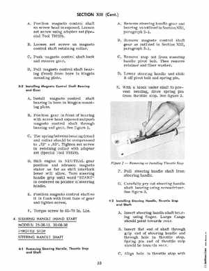
ARemove steering handle gear and bearing as outlined in Section XIII, paragraph 2-1BRemove magneto control shaft gear as outlined in Section XIII, paragraph 3-1Co Remove- stop nut from steering handle pivot boltThen remove retainer and fiber washerDLower steering handle and slide it off pivot bolt and spring pinEWith block under shaft to prevent bending, drive spring pin from throttle stopSee figure 2
AInstall magneto control shaft bearing in bore in kingpin mounting plateBPosition gear in front of bearing with screw head exposed and push magneto control shaft through bearing and gearSee figure 1CThe spring between bearing (rear) and collar should be compressed to .75" ::!: .03"Tighten set screw in retaining collar with adapter set (Special Tool T8929)DShift engine in NEUTRAL gear position and advance magneto stator as far as shift interlock lever will allowTurn steering handle grip until word "START" is centered on pointer of steering handleEPosition magneto control shaft so it is flush with front face of gear and tighten screwFTorque screw to 65-70 InLbs4STEERING HANDLE (HAND START MODELS) 25-08-13, 30-08-38 THROTTLE STOP STEERING HANDLE SHAFT