Chrysler 100, 115 and 140 HP Outboard Motors Service Manual, OB 3439, Page 120Get this manual
Installation Installation
Ends of interlock switch are differentUpper end has two slots and the tab has sharper bend Figure 231Connect yellow (shorter) lead to bottom terminal; and yellow black stripe (longer) lead to upper terminalFigure 232Install switch to bracket and secure with two (2) screwsFigure 23
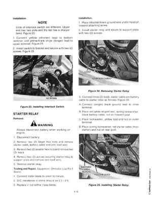
1Place (double) black ground wire under head of forward attaching screw2Install starter relay and secure to support plate with two (2) screws
Figure 24Removing Starter RelaySCREWS
3Connect three (3) leadsstarter cable and battery cable to starter relay as follows: Figure 25
Figure 23Installing Interlock Switch
AConnect (single) black ground lead to inner terminalBPlace redwhite striped lead, spring lockwasher, black battery cable, nut on forward postCPlace lockwasheryellow lead and nut on outer terminal