2003-2005 Kawasaki Ultra-150 Jet Ski Factory Service Manual., Page 20Get this manual
GENERAL INFORMATION 1-15 Technical Information-Engine
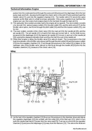
pulses from the crankcase travel through the pulse joint [8] and push the diaphragm [9] in the fuel pump back and forth, drawing fuel through the check valve in the joint [7] and pushing it past the needle valve [11], and into the regulator chamber [12]The needle valve [11] serves the same purpose as the float valve in float bowl-type carburetorIf the pump supplies more fuel than the engine can use, the excess fuel escapes back to the fuel tank through the leak jet [13]3) The carburetor slow system provides fuel to the engine at low speedsThe slow system consists of slow jet [14], various bypass outlets [15], the pilot outlet [16], and the pilot screw [17] As the throttle valve opens, fuel flows through the pilot outlet [16] and then the bypass outlets [15], one by one4) The main system consists of the check valve [18], the main jet [19], the needle jet [20], and the jet needle [21]The jet needle [21] is fixed to the slide and moves with itAs the slide moves, powered by the diaphragm [4-2], the tapered jet needle [21] moves in and out of the needle jet [20] varying the clearance between them and thus the fuel flow out of the needle jet5) When then engine is idling, the throttle valve [3] is almost closedThe low pressure in the inlet tract downstream of the throttle valve draws fuel through the pilot outlet [16] and the bypass outlets [15] from the regulator chamber [12]Even though the pressure in the venturi [2] is higher on the upstream side of the throttle valve, almost no fuel flows through the needle jet [20] and into the regulator chamber [12], because of the check valve [18]