2005-2007 Polaris Ranger 500 service manual, Page 312Get this manual
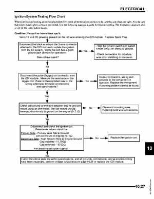
ELECTRICAL Ignition System Testing Flow Chart
Whenever troubleshooting an electrical problem first check all terminal connections to be sure they are clean and tightAlso be sure that colors match when wires are connectedUse the following pages as guide for troubleshootingThe resistance values are also given on the specification pagesCondition: No spark or intermittent sparkVerify 12 Volt DC power is present on the red wire entering the CDI moduleReplace Spark PlugDisconnect the black wire from the wire connector attached to the CDI module to isolate the ignition from the kill systemVerify the CDI has good ground path (Brown) for operationDoes it have spark?Test the ignition switch and speed limiter circuit for shorts to ground- Check connectors for moisture, wire color matching or corrosion
No Disconnect the pulse (trigger) coil connector from the CDI moduleMeasure the resistance of the trigger coilRefer to the exploded view or the wiring schematic for meter connections and specifications?