Kawasaki Prairie 360 KVF-360 Factory service manual, Page 374Get this manual
16-58 ELECTRICAL SYSTEM Actuator Control System
the resistance between Measure lead connector [A]actuator
Special Tool -
the following terminals in the
Hand Tester: 570011394 15 3.5 6.5 630 5,330
Actuator Internal Resistance (Red) (Black): (Orange) (Blue): (Yellow) (Blue):
If any reading is not within the specified range, replace the engine brake actuatorIf the reading is within the specified range, inspect the position of the actuator output shaft as following procedure
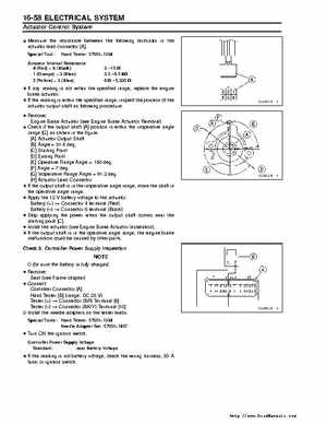
Remove:Brake Actuator (see Engine Brake Actuator Removal) Engine Check if the output shaft [A] position is within the inoperative angle range [G] as shown in the figure[A] Actuator Output Shaft [B] Angle51.4 deg[C] Starting Point [D] Ending Point [E] Operative Range Angle180 deg[F] Angledeg[G] Inoperative Range Angle91.2 deg[H] Actuator Lead Connector If the output shaft is in the inoperative angle range, move the shaft in the operative angle rangeApply the 12 battery voltage to the actuatorConnector terminal (Red) Battery (+) Battery () Connector terminal (Black) Stop applying the power when the output shaft comes near the starting point [C]Install the actuator (see Engine Brake Actuator Installation)If the output shaft is in the operative angle range, the engine brake malfunction could be caused by other parts