2005-2009 Kawasaki Brute Force 650/KVF 650 4x4 Service Manual, Page 440Get this manual
ELECTRICAL SYSTEM 17-61 Meter
Multifunction Meter Unit Inspection
Remove: Multifunction Meter Unit (see Digital Meter Unit Removal)
CAUTION
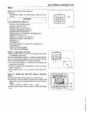
Do not drop the meter unit[A] Meter Unit Lead Connector [1] Speed Sensor Pulse [2] Belt Indicator Light (LED) (-) [3] Water Temperature Sensor (-) [4] 2WD4WD LCD Indicator (-) [5] Fuel Gauge (Fuel Indicator LCD Segments) [6] Meter Illumination (+) [7] Reverse Indicator Light (LED) (-) [8] Neutral Indicator Light (LED) (-) [9] Ignition (+) [10] Battery (+) [11] Oil Pressure Warning Indicator Light (LED) (-) [12] Battery (-) LEDLight Emitting Diode LCD: Liquid Crystal Display
HP20050BSl
Check 1: LCD Segments Check Using auxiliary wires, connect 12 battery to the meter unit connector as follows Connect the battery positive (+) terminal to terminal [10] Connect the battery negative (-) terminal to terminal [12] Connect terminal [9] to the battery (+) terminalOWhen the terminal [9] is connected, all the LCD segments appear for one secondOWhen the terminal [9] is disconnected, all the LCD segments disappearIf this display function does not work, replace the meter unit+12V