2005-2009 Kawasaki Brute Force 650/KVF 650 4x4 Service Manual, Page 161Get this manual
6-10 CONVERTER SYSTEM Torque Converter
Torque Converter Cover Installation
Check the actuator lever assembly installation length (see Torque Converter Cover Assembly) Fit the trim seal into the converter coverOSet the trim seal juncture in the area [A] when insert the trim seal in the cover[B] 10 mm (0.39 in
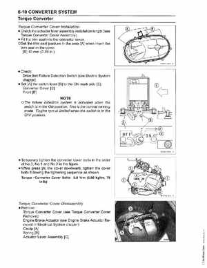
Check: Drive Belt Failure Detection Switch (see Electric System chapter) Set [A] the switch lever [B] to the ON mark side [C] Converter Cover [0] Front [E]
failure detection system is activated when the switch is in the ON positionThis is the normal running modeEngine rpm is limited when the switch is in the OFF position