2005-2009 Kawasaki Brute Force 650/KVF 650 4x4 Service Manual, Page 141Get this manual
ENGINE TOP END 5-33 Valves
Marks Stamped on the Cutter The marks stamped on the back of the cutter [A] represent the following 60 Cutter angle [8] 37.5 Outer diameter of cutter [C]
GE1501 8S1
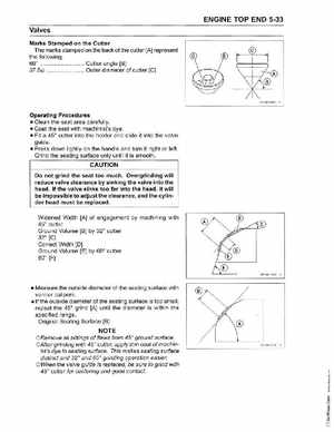
Operating Procedures Clean the seat area carefully Coat the seat with machinist's dye Fit 45 cutter into the holder and slide it into the valve guide Press down lightly on the handle and turn it right or leftGrind the seating surface only until it is smooth
CAUTION
Do not grind the seat too muchOvergrinding will reduce valve clearance by sinking the valve into the headIf the valve sinks too far into the head, it will be impossible to adjust the clearance, and the cylinder head must be replaced
Widened Width [A] of engagement by machining with 45 cutter Ground Volume [8] by 32 cutter 32 [C] Correct Width [0] Ground Volume [E) by 60 cutter 60 [F)