2005-2009 Kawasaki Brute Force 650/KVF 650 4x4 Service Manual, Page 135Get this manual
ENGINE TOP END 5-27 Cylinder Head
Cylinder Head Removal
Drain the coolant (see Coolant Change in Periodic Maintenance chapter) Remove: Carburetor (see Carburetor Removal in Fuel System chapter) Exhaust Pipe (see Exhaust Pipe Removal) Water Pipe [A] Spark Plug Cap [B) Rocker Case [C] Camshaft (see Camshaft Removal) Remove: Cylinder Head Bolt (M6) [A] Cylinder Head Bolts (M 1O) [B) and Washers Cylinder Head [C] and Gasket OLift the cylinder head to clear the dowel pins in the cylinder, and slide the cylinder head out of the frame
Cylinder Head Installation
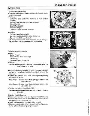
Install: Dowel Pins [A] New Cylinder Head Gasket [B) Oil Pipe [C] Camshaft Chain Guides [D) Tighten:
TorqueFront Cylinder Camshaft Chain Guide Bolt: 20 N-m (2_0 kgf-m, 14 ft-Ib)
Apply molybdenum disulfide oil to the threads and seating surface of the cylinder head bolts and both sides of the washers_ Tighten the cylinder head bolts following the tightening sequence as shownFirst TorqueCylinder Head Bolts (M10) [A]: 25 N-m (2_5 kgf-m, 18 ft-Ib) Final TorqueCylinder Head Bolts (M10) [A]: 49 N-m (5_0 kgf-m, 36 ft-Ib)